
In engineering and manufacturing, accuracy is not a concept, it is a measurable requirement. For a sheet metal part to fit, operate, and perform as desired, the physical properties of any component must fall within a range of defined limits. Tolerances are the controlling factors in this important concept in the field of sheet metal manufacturing. Sheet metal tolerances are essential knowledge to designers, engineers, and procurement specialists. It is the language that bridges the gap between design intent and manufacturing reality, and has a direct impact on the assembly, performance, quality and end cost of a product.
This guide is a practical and detailed discussion of sheet metal tolerances. We shall cut them open to see what they are, we shall consider the myriads of factors, including different metals and sheet metal thickness, which affect them, we shall give standard values of common materials and processes, and we shall talk of the industry standards which regulate their use. The goal is to provide you with the knowledge to design something that is functional and manufacturable and to communicate with fabrication partners in an effective and clear way.
What Are Sheet Metal Tolerances?
The allowable limit or range of variation in a particular dimension or geometric feature of a fabricated part is called a sheet metal tolerance. Essentially, it is the degree to which the measurement of a finished part may vary with respect to the nominal value given on an engineering drawing without affecting the functionality of the part. As an example, a drawing may indicate that a part is 100 mm long. A related tolerance of +/- 0.2 mm means that any completed part between 99.8 mm and 100.2 mm is acceptable.
The need to have tolerances is based on a very simple fact that it is impossible to achieve perfection in manufacturing and it is not economically feasible. There are natural, small differences in every fabrication process, including cutting and bending. These minor deviations are caused by tool wear, machine calibration, material inconsistencies, and environmental factors.
Tolerances have two functions. First, they give a clear, unambiguous goal to the manufacturer regarding the design requirements, which sets the limits of the acceptable quality. Second, they provide the designer with control over the most important features of a part’s fit and functionality. The designer can provide the product performance and control the manufacturing costs by assigning tighter tolerances to features that are critical to alignment or assembly and looser tolerances to features that are not critical. A part with no well-defined tolerances is a part that is left to chance, and may result in assembly failures, functional defects, and project delays.
Types of Sheet Metal Tolerances
Tolerances are not a single concept; they are divided according to the feature they govern. A complete design needs a mixture of these types to completely specify the acceptable geometry of a part.
Dimensional Tolerances
This is the most prevalent form of tolerances and they are applicable to the linear and angular measurements of a part. They dominate in size.
- Bilateral Tolerances: The tolerance is allowed in both directions, positive and negative, of the nominal dimension (e.g., 50 mm +0.1 mm -0.1 mm). It is the most common format.
- Unilateral Tolerances: The variation is allowed in one direction only with respect to the nominal dimension (e.g., 20 mm +0.2/-0.0 mm). It is commonly applied where a clearance or interference fit is to be ensured in a single direction.
- Limit Dimensions: The upper and lower limits are given directly and no calculation is required (e.g., 49.9 mm – 50.1 mm). It is the most unambiguous and explicit method of expressing a dimensional tolerance.
Geometric Dimensioning and Tolerancing (GD&T)
Whereas dimensional tolerances govern the size of features, geometric tolerances govern their form, orientation and location. This system offers a far more accurate method of specifying the functional requirements of a part. The most important ones are:
- Flatness: Regulates the departure of a surface to an ideal plane.
- Perpendicularity: Regulates the proximity of a surface or axis to an ideal 90-degree angle with respect to a datum.
- Parallelism: Regulates the parallelism of a surface or axis to a datum plane or axis.
- Position: Specifies a range over which the axis or center plane of a feature may be allowed to deviate relative to its actual (theoretically accurate) location.
- Profile of a Surface: Defines a uniform boundary on a surface in which the elements of the surface have to be contained.
GD&T is a tool that cannot be ignored in complex sheet metal assemblies where the relationship of features is paramount.
Key Factors Influencing Sheet Metal Tolerances

The ultimate tolerable value on a sheet metal component is not a random selection but a complicated interrelation of physical and procedural variables. It is important to consider these variables at the design stage to have realistic expectations.
Material Properties and Thickness
The kind of sheet metal is a major factor that determines the precision that can be achieved. The softer materials such as aluminum are more likely to be deformed in the process of processing as compared to harder materials such as steel. Moreover, the material characteristics, including ductility and hardness, influence the material behavior under cutting, punching, and bending loads. The thicker sheets take much more force to process and this may cause more variability in the process and larger tolerance ranges. The ability to control the bend angle of a 3 mm thick steel plate is a completely different task compared to the ability to control a 0.8 mm thick aluminum sheet.
Fabrication Processes and Equipment
There is a certain degree of accuracy in every fabrication process. The accuracy of modern fiber laser cutters is very high, typically better than +/- 0.1 mm, whereas a manual shearing operation may only be accurate to +/- 1.0 mm. Likewise, an automated CNC press brake with automated backgauges and angle correction systems can maintain bend angle tolerances much tighter than a manual brake. The selection of the process is a direct trade-off between the accuracy needed and the expense of the process.
Machine Capabilities and Calibration
In addition to the kind of equipment, it is important to note the condition of the machine. A machine that is in good shape and is frequently calibrated will result in high repeatability and accuracy of the parts. Tooling that is worn, machine parts that are not aligned, or control systems that are not accurate will add errors that will not allow tight tolerances to be held. A good fabricator will spend a lot of money on machine maintenance and a strict calibration program to make sure that what they claim to be able to do is actually done.
Springback Effect
In bending, the metal is deformed past its elastic limit to permanently deform. But when the bending force is released, the material tends to partially regain its original shape. A 90-degree bend may slacken to 91 or 92 degrees. This is called springback. It plays an important role in the attainment of correct bend angles. To compensate, fabricators have to deliberately over-bend the material by a measured degree. Springback depends on the type of material, thickness, bend radius, and tooling, so angular tolerances are naturally more difficult to control than cutting tolerances in a straight line.
Thermal Deformation
Thermal stress is introduced into the material by processes that produce a lot of heat, e.g. laser cutting and welding. When the metal is hot, it expands; when it is cold, it contracts. This cycle may result in warping, bowing and alteration of the final dimensions, especially in thin materials or large parts. The region influenced by this heat is referred to as the Heat-Affected Zone (HAZ) which can also have changed material properties. Experienced fabricators employ certain methods to reduce these effects; however, thermal deformation is a major cause of variation.
Grain Direction
The sheet metal has a grain direction, which is a consequence of the rolling process when it is made. The mechanical properties of the material such as its bending properties, may vary when the bend is done parallel, perpendicular, or diagonal to this grain. Bending parallel to the grain (“with the grain”) may result in a greater, more variable bend radius and even cracking on the outside of the bend. To achieve repeatability, designers are advised, where feasible, to orient parts in such a way that bends are formed across the grain of the material.
Design Complexity
In general, the more complicated the part, the harder it is to maintain tight tolerances throughout the geometry. Every bend, hole, and feature is another possible source of variation. These variations of individuals can add up throughout the part in what is referred to as ”tolerance stack-up”. The tolerance of two holes on a flat plate may be +/- 0.1 mm, but when the holes are on different flanges with three bends between them, the tolerance between the holes will be much wider as the variation of each bending operation is added to the variation of the other. This highlights the importance of design guidelines that consider complexity.
Manufacturer’s Expertise and Quality Control
Finally, the fabricator has the capability of maintaining a given tolerance. A skilled crew is familiar with the peculiarities of the behavior of various materials on their particular equipment. They possess strong machine calibration, tool maintenance and consistency processes. A strict quality control regime, frequently certified to standards such as ISO 9001, makes sure that parts are checked at key points and that processes are constantly checked and refined. The experience of the manufacturer is the element that unites and regulates all the above-mentioned variables.
Common Material Choices and Their Tolerances
One of the initial and most important decisions in sheet metal design is the selection of material. Every material has a specific strength, weight, corrosion resistance and workability and this directly influences the tolerances that can be attained reliably.
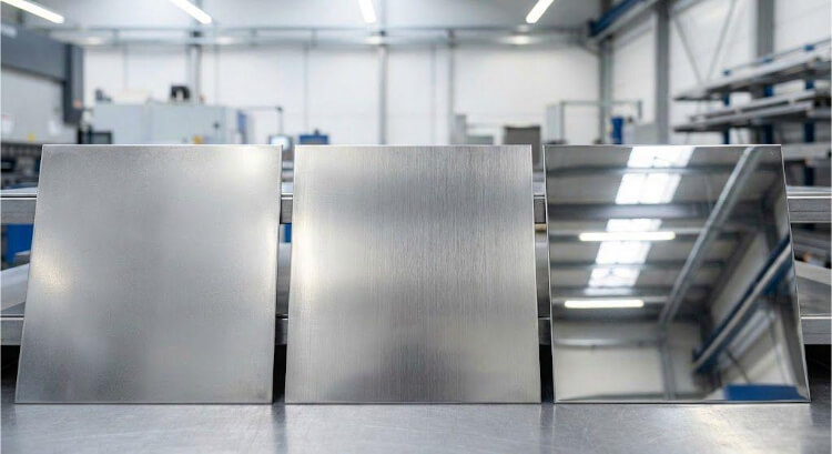
Material Types
- Carbon Steel (e.g., A36, 1018): Durable, economical, and common. It is fairly stable in processing, but is heavy and prone to rust unless it is given a protective finish.
- Stainless Steel (e.g., 304, 316): Provides high corrosion resistance and strength. It is more difficult to bend than carbon steel and has greater springback, so tight bend tolerances are more difficult to attain.
- Aluminum (e.g., 5052, 6061): Lightweight, naturally corrosion-resistant, and possesses good thermal conductivity. It is less hard and difficult to shape than steel but more prone to thermal deformation and scratches.
- Copper & Brass: These are appreciated due to their high electrical and thermal conductivity. They are malleable and very easy to shape but also more costly and can easily be deformed unless handled with care.
Material Tolerance Properties
The assumption that a material has one tolerance value is wrong. Rather, the designer ought to take into consideration its intrinsic characteristics. The following table summarizes some of the important properties that determine the behavior of these materials during fabrication. Tolerance Sensitivity is a qualitative indicator of the difficulty of maintaining tight tolerances with that material, taking into account such factors as springback and thermal effects.
| Material | Tolerance Sensitivity | Typical Tolerance Range | Elastic Modulus (GPa) | Thermal Expansion Coefficient (10⁻⁶/°C) |
| Carbon Steel (Mild) | Low | ±0.1mm to ±0.3mm | 200 | 12.0 |
| Stainless Steel 304 | Medium | ±0.1mm to ±0.4mm | 193 | 17.2 |
| Aluminum 5052-H32 | Medium-High | ±0.1mm to ±0.5mm | 70 | 23.8 |
| Copper C110 | High | ±0.15mm to ±0.5mm | 117 | 16.5 |
Note: The Typical Tolerance Range is for general linear dimensions on a single plane for sheet thicknesses around 1-3mm. These values are illustrative and can be influenced by all the factors mentioned previously.
Standard Tolerances by Fabrication Process

The fabrication method is a dominant factor in the precision of the final product. Here are the typical tolerance capabilities of common sheet metal processes.
Laser Cutting Tolerances
The modern laser cutters employ a highly focused beam of light to melt and vaporize the material, providing outstanding precision and clean edges with a minimal heat-affected zone (HAZ). Nevertheless, precision is not consistent and depends on the dimension size in general and the specific features themselves.
In smaller linear dimensions (below 100 mm), a close tolerance of +/- 0.05 mm to +/- 0.1 mm is normal. The larger the dimension (more than 100 mm), the greater the possibility of variation throughout the travel of the machine head, and the tolerance is broadened to +/- 0.5 mm. The same reasoning can be applied to hole diameters, where a smaller hole can frequently be tighter than a larger one.
Punching Tolerances
CNC turret punching is a fast and very repeatable process that punches features into a sheet with a library of hardened tools. In general, linear dimensions, tolerances are usually a little looser than laser cutting, usually between +/-0.1 mm and +/-0.5 mm, and strongly dependent on the accuracy of the die and the thickness of the material. The hole diameter is normally uniform at +/- 0.1mm to +/- 0.2mm.
Hole position is a critical consideration in punching. Although a single punch is very precise, a series of punches over a section may cause cumulative error, which causes a positional tolerance of +/- 0.13 mm to +/- 0.25 mm.
Bending Tolerances
The most important process that influences the final geometry and where material properties have the most influence on tolerances is bending.
- Angle Tolerance: Bend angles are usually tolerated to +/- 0.5 to +/- 1.0 degrees because of the type of material, thickness, and the springback effect.
- Linear Dimension (Post-Bend): Dimensions between bends are influenced by the material stretching that takes place during forming. As a result, the tolerance of linear dimensions of one or more bends is broader, typically between +/- 0.3 mm and +/- 0.8 mm.
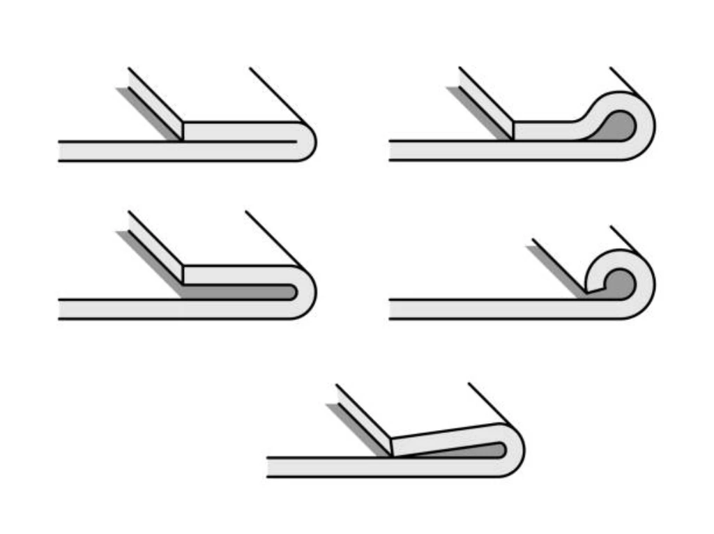
Stamping and Forming Tolerances
Stamping uses custom-made dies to form parts at high speed. The initial cost of the die is high, but the per-part cost is very low for high-volume production. While basic linear dimensions and hole diameters can maintain tolerances of ±0.1 mm to ±0.5 mm, similar to punching, this process also includes complex forming operations.
The tolerances for these formed features are naturally wider, ranging from ±0.2 mm to ±0.8 mm, as they are highly dependent on material ductility and the specific design of the forming die. This can include features like tabs, overhangs, hemming, and the formation of a curl or hem.
Welding Tolerances
Welding introduces significant localized heat, causing thermal expansion and contraction that leads to distortion. It is therefore the least precise of the common fabrication processes. The extent of this distortion is directly related to the scale of the work. For short weld lengths or precisely fixtured components (under 100mm), tolerances of ±0.5 mm to ±1.0 mm might be achievable. For longer weld seams or complex assemblies, the effects of heat distortion become much more pronounced, requiring significantly looser tolerances in the range of ±1.0 mm to ±2.0 mm.
General Tolerances for Sheet Metal Fabrication Process
| Process Type | Feature | Typical Tolerance (mm / °) | Remarks |
| Laser Cutting | Linear Dimension (< 100mm) | ±0.05 ~ ±0.1 | High precision; affected by material thickness. |
| Linear Dimension (> 100mm) | ±0.1 ~ ±0.5 | The larger the dimension, the wider the tolerance. | |
| Hole Diameter (e.g., < 5mm) | ±0.05 ~ ±0.1 | Depends on material thickness; smaller holes can be tighter. | |
| Hole Diameter (e.g., > 5mm) | ±0.1 ~ ±0.15 | ||
| Punching | Linear Dimension (General) | ±0.1 ~ ±0.5 | Dependent on die precision and material thickness. |
| Hole Diameter | ±0.1 ~ ±0.2 | Depends on die condition; smaller holes often have tighter tolerances. | |
| Hole Position | ±0.13 ~ ±0.25 | High precision for single hits; error can accumulate in series. | |
| Bending | Angle Tolerance | ±0.5° ~ ±1.0° | Affected by material type, thickness, bend radius, and springback. |
| Linear Dimension (Post-Bend) | ±0.3 ~ ±0.8 | Especially for distances between bent features, material stretch varies. | |
| Forming | Formed Feature Dimension | ±0.2 ~ ±0.8 | Tolerances for embosses, draws, etc., are wider; depends on material ductility. |
| Boss Height / Countersink Depth | ±0.2 ~ ±0.5 | Dependent on feature complexity and material. | |
| Stamping | Linear Dimension (General) | ±0.1 ~ ±0.5 | Highly dependent on die precision and material thickness. |
| Hole Diameter | ±0.1 | ||
| Welding | Short Weld / Simple Fixture (< 100mm) | ±0.5 ~ ±1.0 | Thermal distortion is relatively contained. |
| Long Weld / Complex Assembly (≥ 100mm) | ±1.0 ~ ±2.0 | Thermal effects are more significant, requiring looser tolerances. |
Industry Standards and Guidelines for Sheet Metal Tolerances
To ensure clear communication between designers and manufacturers, several industry standards have been developed.
ISO 2768
This is an international standard that specifies general tolerances for linear and angular dimensions, as well as geometric tolerances for features produced by metal removal (machining) or forming processes. It provides a simplified way to tolerate a part without specifying a tolerance for every single dimension. ISO 2768 defines several tolerance classes:
- f (fine)
- m (medium)
- c (coarse)
- v (very coarse) A note on a drawing such as “Tolerances to ISO 2768-m” applies the medium tolerance class to all dimensions that do not have a specific tolerance indicated.
ASME Y14.5
This is the authoritative standard for Geometric Dimensioning and Tolerancing (GD&T) in North America. It does not provide tolerance values. Instead, it provides the symbolic language, rules, and definitions for specifying geometric controls. It is the framework that allows a designer to precisely define the functional requirements of a part far beyond what is possible with simple dimensional tolerances.
Key DFM Tips for Sheet Metal Design
Designing for Manufacturability (DFM) is the proactive design of parts so that they are simpler and less expensive to manufacture. It is important to apply DFM principles to tolerances.
- Tolerances: The golden rule is to specify them as loosely as possible. Use tight tolerances only where necessary to perform a functional requirement. One of the most frequent causes of unnecessary cost is over-tolerancing.
- Standard Bend Radii: Standard tooling of a fabricator determines the most efficient bend radii. Designing to a 1.0 mm inside bend radius, as an example, is much more efficient than specifying a non-standard 1.3 mm radius that might need special setup.
- Avoid Holes in Bends: Holes should be at least 2 to 3 times the thickness of the material away from the bend edge. Holes that are too close may get distorted in the process of bending.
- Keep Bend Orientations Consistent: Whenever possible, orient all bends in the same direction to avoid re-orientation of parts in the press brake, which is time-consuming and expensive.
- Talk to Your Fabricator Early: Discuss with your manufacturing partner at the design stage. They are able to give you priceless advice on the manufacturability of your design and assist you in setting tolerances that are practical and cost-effective.

The Direct Link Between Tight Tolerances and Cost
There is a direct and exponential relationship between the tightness of a tolerance and the cost of fabrication. Halving a tolerance does not double the cost; it can increase it by a factor of four, five, or even more. Moving from a standard tolerance (e.g., ±0.2 mm) to a tight tolerance (e.g., ±0.1 mm) might increase the cost by 25%. Moving to a precision tolerance (e.g., ±0.05 mm) could double or triple the cost.
This cost increase is driven by several factors:
- Slower Production Speeds: To achieve higher precision, machines must often run at slower speeds.
- Increased Setup and Calibration Time: More time must be spent ensuring the machine is perfectly calibrated and the setup is exact.
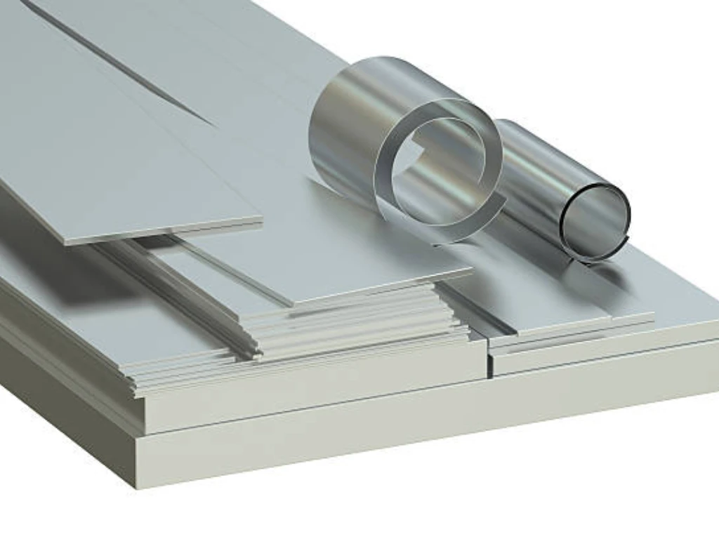
- Advanced Equipment Requirement: Holding very tight tolerances may require more expensive, higher-precision machinery, such as precise rollers for forming sheets of metal.
- Higher Inspection Costs: Parts must be inspected more frequently and thoroughly, often with more sophisticated metrology equipment.
- Increased Scrap Rate: The probability of a part falling outside a very narrow acceptance window increases, leading to more scrap.
A designer who understands this relationship can make informed decisions, balancing the need for precision of sheet metal parts with the constraints of the project budget.
Achieving Your Specs with TZR’s Expert Fabrication
When it comes to precision sheet metal fabrication, your design is only as good as the team that brings it to life. At TZR, we turn detailed blueprints into reality through a blend of advanced machinery, strict process control, and skilled craftsmanship. Serving industries like automotive, medical devices, 3D printing, and renewable energy, we specialize in working with steel, stainless steel, aluminum, copper, and brass—delivering parts that meet demanding specifications without compromising efficiency or budget. This ensures the durability and reliability of sheet metal components in the final product.
Our experienced engineers partner directly with you to review your designs and provide critical DFM (Design for Manufacturability) feedback, ensuring your specified tolerances are practical and cost-effective. With precision capabilities up to ±0.02mm and a 98% yield rate, we’re committed to delivering consistent quality, even for complex bends and tight angles, while minimizing marks and defects. Backed by 25 years of sheet metal fabrication experience and ISO 9000 standards, TZR helps you navigate the challenges of precision fabrication.
If you are developing a project that requires precise sheet metal components, we invite you to contact our engineering team. Let us help you navigate the complexities of fabrication and deliver parts that meet your exact specifications.
Conclusion
Sheet metal tolerances are far more than mere numbers on a drawing. They are the foundational elements that ensure functionality, guide the manufacturing process, and control the final cost of a component. A thorough understanding of the different types of tolerances, achievable tolerances, and the many factors that influence them, and the industry standards that govern them is essential for any professional involved in product development.
By designing with manufacturability in mind, specifying tolerances only as tight as functionally necessary, and collaborating with a knowledgeable fabrication partner, you can create products that are robust, reliable, and economically viable. Mastering the principles of tolerancing is a direct investment in the quality and success of your projects.