
Sheet metal bending is one of the most common processes in fabrication and manufacturing industries. This process makes it possible to produce accurate, useful, and long-lasting parts. It is important to understand the details of the bending of sheet metal to ensure that the final products are of high quality and, at the same time, the cost of production is low. It is always important to continue learning no matter how new or old you are in the industry.
What can you get from this post?
- The principles of sheet metal bending.
- Various bending processes and the applications of each.
- The materials used in bending and their characteristics.
- How sheet metal bending is used in different fields.
- The important factors to consider when designing for bending.
- Optimizing designs for cost, quality, and manufacturability (DFM).

What is Sheet Metal Bending?
Sheet metal bending involves applying force to a sheet of metal, bending it at a specific angle without breaking. Essentially, it transforms a flat sheet into a part with a desired sheet metal bend, similar to folding paper but with precision. The material goes through plastic deformation, allowing it to change shape.
Sheet metal bending is commonly used on materials that are between 0.5mm and 6mm thick. However, this can depend on the type of material. Mild steel, stainless steel, and aluminum are often used, and each of them reacts differently when force is applied.
The process is highly versatile. It enables the formation of different shapes within a short time and without the need for costly molds, which makes it suitable for making parts as and when they are required. It is also very accurate and highly repeatable, which means that the results obtained are always reliable. When properly done, the process is cost-effective for both small and medium production volumes, thus minimizing wastage of materials.
Industries That Rely on Sheet Metal Bending
The versatility of sheet metal bending makes it vital across multiple industries. It allows for precise shapes and angles, which are hard to achieve with other methods. The bending process enables the creation of parts needing features like flanges, notches, lips, and interlocking joints. These features enhance strength, improve fit, and boost functionality.
| Industry | Industry Needs | How Sheet Metal Bending Addresses These Needs | Common Components Produced |
| Automotive | High durability, lightweight, and precise parts | Bending creates precise angles for structural components without sacrificing strength | Car frames, body panels, brackets |
| Aerospace | High precision, material strength, and weight control | Enables accurate bends for lightweight, durable parts | Aircraft fuselages, wing sections |
| Electronics | Precision and compact designs for tight spaces | Bending allows for intricate, compact designs with tight tolerances | Casings, circuit board enclosures |
| Medical Devices | Need for high precision and regulatory compliance | Provides precise, repeatable bends to meet stringent medical standards | Medical housings, surgical tools |
| Household Appliances | Efficiency in manufacturing and space efficiency | Allows the rapid production of parts with specific functional features | Refrigerator panels, oven bodies |
| Industrial Equipment | Durability, functionality, and cost-efficiency | Bending enables the manufacturing of heavy-duty, precise components | Machine frames, brackets, guards |
| Construction | Custom sizes and fast production for varied needs | Flexible design options and fast turnaround without complex tooling | HVAC ducts, custom structural parts |
The table above provides a concise overview, but the true importance of sheet metal bending becomes clearer when we explore how it solves the fundamental challenges within each industry.
Automotive
In the auto industry, this process is foundational. It enables the creation of lightweight components from high-strength steel, which is essential for boosting fuel economy and meeting emissions standards. Critically, it also forms the vehicle’s safety cage and crumple zones, which are non-negotiable for passing rigorous crash test regulations.
Aerospace
For aerospace, where every gram matters, bending provides an unmatched strength-to-weight ratio. It shapes lightweight alloys for frames and wings without compromising the material’s structural integrity, directly improving fuel efficiency and payload capacity.
Electronics
In electronics, bent metal enclosures provide essential EMI/RFI shielding, a requirement for passing regulatory compliance like FCC and CE. The process also creates integrated features for heat dissipation and airflow management, ensuring long-term component reliability.
Medical
The medical field relies on bending to create components with smooth, crevice-free surfaces from materials like stainless steel and titanium—a prerequisite for effective sterilization. Its high repeatability ensures the part-to-part consistency required to pass stringent FDA and CE validation, guaranteeing patient safety.
Household Appliances
For household appliances, bending is key to both aesthetics and manufacturing efficiency. It enables the rapid, cost-effective production of durable frames and visually appealing exterior panels for products like refrigerators and ovens, meeting the high-volume demands of the consumer market.
Industrial Equipment
Industrial equipment depends on bending to create robust, heavy-duty frames, brackets, and safety guards. The process turns thick metal sheets into durable structural components that withstand demanding operational stresses, ensuring machinery longevity and operator safety.
Construction
In construction, bending allows for the rapid, on-demand fabrication of custom structural supports and architectural panels, enabling design freedom without sacrificing integrity. It is also the only viable method for producing long, continuous elements like gutters and flashing, ensuring a building’s long-term durability and weather resistance.
In short, sheet metal bending is far more than a simple forming technique; it is a critical enabler of modern innovation, safety, and efficiency.
How Sheet Metal Bending Works
The process of bending sheet metal is precise and requires careful planning. It begins with the design phase. In this phase, a DFM analysis is performed to check whether the part can be manufactured efficiently and whether it meets all the specifications. After the design is done, the next process is to choose the right tooling. This involves selecting the die and punch depending on the type of material, thickness and the required bend.
After the tooling is set up, the machine parameters are then adjusted. The press brake, which is a frequently used bending machine, is then prepared. The sheet metal is then positioned on the tooling and the machine exerts pressure on the metal in a controlled manner. When the press brake is in motion, the material bends in the right manner along the bend line that has been provided.
The operator ensures that the metal is well-positioned in order to avoid any distortion that may lead to warping of the part. When the bend is complete, the sheet metal is removed. The same is done for any other bends that may be required. All these make it possible for manufacturers to produce quality parts that meet the required specifications in the production process. At TZR, our engineers leverage their extensive experience to deeply analyze your specific design and materials, thereby creating the optimal manufacturing solution to guarantee the final product’s precision from the very start.

Types of Sheet Metal Bending Techniques
Different bending techniques are used depending on the shape, material, and requirements of the part being fabricated. Understanding these techniques is vital for selecting the appropriate method for each project.
V-Bending
V-bending is the most common category of sheet metal bending. In this process, a punch presses the sheet metal into a V-shaped die. The final angle is determined by the depth and force with which the punch presses the material into the die, which varies depending on the specific technique used. This makes V-bending highly effective for creating a wide range of precise bends. There are three primary methods within V-bending, each offering a different balance of precision and force:
Air Bending
Air bending is a V-bending method where the punch presses the sheet metal into a die without making full contact with the bottom; it is literally ‘bent in the air.’ The final angle is determined by the punch’s stroke depth, not the die’s angle. The primary advantages of air bending are its flexibility—allowing various angles to be formed with a single toolset—and its low force requirement. However, this flexibility comes at the cost of lower precision, as it is more susceptible to springback than other methods.
- Advantages: High flexibility, lower tonnage required, faster setup.
- Common Uses: The most common bending method for general fabrication and prototypes where slight angular variations are acceptable.
Bottoming
In this method, the punch presses the material downwards until it makes full contact with the V-die’s inner surfaces, forcing the material to conform to the precise angle of the die. Bottoming offers better accuracy and repeatability with less springback than air bending.
- Advantages: Higher accuracy and repeatability than air bending.
- Common Uses: Parts that require more precise angle control than standard air bending can offer.
Coining
This is a high-precision, high-tonnage process. The punch exerts extreme pressure, stamping the material and forcing it to fully conform to the die. This process thins the material slightly at the bend and virtually eliminates springback, resulting in very high angular accuracy.
- Advantages: Highest precision and almost no springback.
- Common Uses: Applications requiring extremely tight tolerances, such as in the aerospace or medical device industries.
Edge Bending
Edge bending is applied when a bend is required at the edge of the sheet of metal. This method is widely used for the manufacturing of flanges and other parts where the bend has to be made at the edge of the material. The process usually involves using a press brake with a die that enables the edge to be bent while the rest of the sheet remains unaffected.
- Advantages: Effective for creating bends with a large inside radius, avoids marking the face of the sheet.
- Common Uses: Creating edge flanges on panels, reinforcing lips, and manufacturing shallow channels near the edge of a part.
U-Bending
U-bending is similar to V-bending, but the die used has a U-shape as opposed to the V-shape used in V-bending. This technique is used in making circular bends such as those of tubes and pipes. U-bending is used in the manufacturing of parts that have small radii or curves and it is ideal when used in the manufacturing of bent sheet metal parts that are required to fit in a joint or frame.
- Advantages: Highly efficient for forming parts with two parallel bends in a single operation, ensures excellent parallelism.
- Common Uses: Manufacturing U-channels, stiffening brackets, and frame components requiring a specific channel width.
Roll Bending
Roll bending is the process of bending sheet metal through the use of rollers that help to gradually shape the material into a curved form. This technique is widely applied for making large and smooth bends, such as those used in cylindrical parts or curved panels. Roll bending is most suitable for making gradual bends that need a constant radius along the length of the material.
- Advantages: Perfect for creating large-radius curves without custom dies, can form complete cylinders or cones.
- Common Uses: Fabricating cylindrical tanks, conical hoppers, curved architectural panels, and large-diameter pipes.
Materials Used in Sheet Metal Bending
The type of material used in sheet metal bending greatly determines how the material will behave when bent. Some of the most used materials in sheet metal fabrication include mild steel, stainless steel, and aluminum, among others, all of which have different characteristics. The tensile strength and hardness of the material also influence the type of tooling and the force that is required to make a proper bend. Another factor that needs to be taken into account when selecting the material is the thickness of the material to be bent. Thicker materials are more rigid and may need more force to bend and the bending radius may also have to be changed. Below are the comparisons of some of the most commonly used materials in sheet metal bending:
| Material | Bending Difficulty | Key Characteristics | Common Applications |
| Mild Steel | Easy | Ductile, affordable, good for general use | Automotive parts, frames |
| Stainless Steel | Moderate | High tensile strength, corrosion-resistant | Kitchen appliances, medical tools |
| Aluminum | Easy | Lightweight, corrosion-resistant, easily formable | Aerospace, electronics enclosures |
| Copper | Moderate | Good thermal conductivity, soft but relatively expensive | Electrical components, HVAC |
| Brass | Moderate | Corrosion-resistant, ductile | Decorative items, marine parts |
| Galvanized Steel | Moderate | Coated with zinc for rust resistance, tougher to bend | Roofing, gutters |
| Titanium | Hard | Extremely strong and lightweight, expensive | Aerospace, medical implants |
| Carbon Steel | Easy | High strength, affordable, but prone to rust | Heavy machinery, construction |
Design Considerations for Sheet Metal Bending
There are several factors that should be taken into consideration when designing a part for sheet metal bending so that the part can be functional and producible. These factors influence the feasibility of the bending process and the quality of the final product.
Bend Radius
The bend radius refers to the inside radius of the bend. It is important for the strength and integrity of the final part. A smaller radius can lead to cracking or breaking of the material because the stress is focused in that region. Hence, the right bend radius should be chosen to avoid such mishaps.
It is advisable that the bend radius should be at least equal to the thickness of the material being bent. For instance, if the thickness of the sheet is 1mm, then the bend radius should not be less than 1mm. This makes sure that the metal can bend without breaking or getting a wrong shape that is not required. There is a standard formula that can be used to determine the bend radius and it is as follows:
Bend Radius = Material Thickness × K
Here, K is a constant based on the material type (it is usually in the range of 0.8 to 1.5). For softer materials such as aluminum, a small constant is used, while for harder materials such as steel, a large constant is used. For more details about choosing the right sheet metal bending radius, you can click to read the post!

Springback
Springback is the tendency of the material to revert back to its original shape after having been bent. This is because metals such as steel and aluminum are elastic materials and they have the capacity to regain their original shape once the force that was applied to bend them is released. Springback should also be considered in the design because the final part may have an angle that is less than the design value.
To minimize springback, one of the methods is to bend the material slightly more than the required angle as the material will try to return to its original position. The degree of over-bend that is needed is dependent on the type of material, the thickness of the material, and the angle of bend. For instance, if you want to bend the material at 90 degrees, you may bend it to 92 degrees and then allow the springback to correct the angle to 90 degrees. It is advisable to perform test bends to establish the amount of springback that should be expected before the final production. Also, some of the methods such as air bending or bottoming can be employed to reduce spring back and thus have better control of the final dimensions of the product.
Bend Allowance
Bend allowance is the extra length of material needed to allow for the stretch or compression that occurs when the sheet metal is bent. In the bending process, the inner surface of the material is subjected to a compressive force while the outer surface is subjected to a tensile force. This change in material shape will affect the total length of the part and this aspect has to be considered to arrive at the correct dimensions.
Bend allowance is an important factor that must be determined correctly to ensure that the parts fit well during assembly. If the bend allowance is wrong, the parts will be too long or too short and this will result in gaps, misalignment or poor fit. This can lead to assembly problems or defects in the final product, which may be very expensive and time-consuming to rectify.
To calculate bend allowance, you can use the following formula:

Where:
- Radius refers to the inside radius of the bend.
- Material Thickness is the thickness of the sheet metal.
- Angle is the angle of the bend in degrees.
This formula is useful for determining the extra length required for a particular bend, which is useful when creating flat patterns or expanding them for cutting. For those who are not familiar with the bend allowance, there are online calculators and bending charts that can be of help. These tools often contain material constants (for example, the K-factor) that may differ depending on the material. It is advisable to check with the material supplier for the right K-factor to avoid making mistakes in calculations.
If you’re working with a professional sheet metal shop, these calculations will often be handled for you, allowing you to focus on your design while the experts take care of the details.
Bend Deduction
Bend deduction is the amount of material that is removed from the length of the flat pattern when the material is bent. Proper bend deduction helps in achieving the correct dimensions of the part and also helps in avoiding wastage of material in the bend. This is usually determined by the bend radius and the thickness of the material to be bent. In general, the larger the bend radius and the thicker the material, the greater the deduction needed. The formula for bend deduction is:

This formula enables you to determine the amount of material that has to be trimmed to ensure that the part has the right dimensions. When designing, it is important to consider the number of bends in a part. Each bend affects the length, so for parts that have more than one bend, the deductions should be adjusted to ensure that there are no variations. Knowledge of bend deduction helps to make sure that the design created is correct and can be manufactured without issues.
K-Factor
The K-Factor is a crucial coefficient used to accurately calculate the flat pattern length of a bent part. During a bend, the inner material compresses while the outer material stretches. The Neutral Axis is an imaginary plane within the material that does neither.
The K-Factor defines the location of this Neutral Axis. It is a ratio of the distance from the inside face to the Neutral Axis (t) divided by the total material thickness (T):
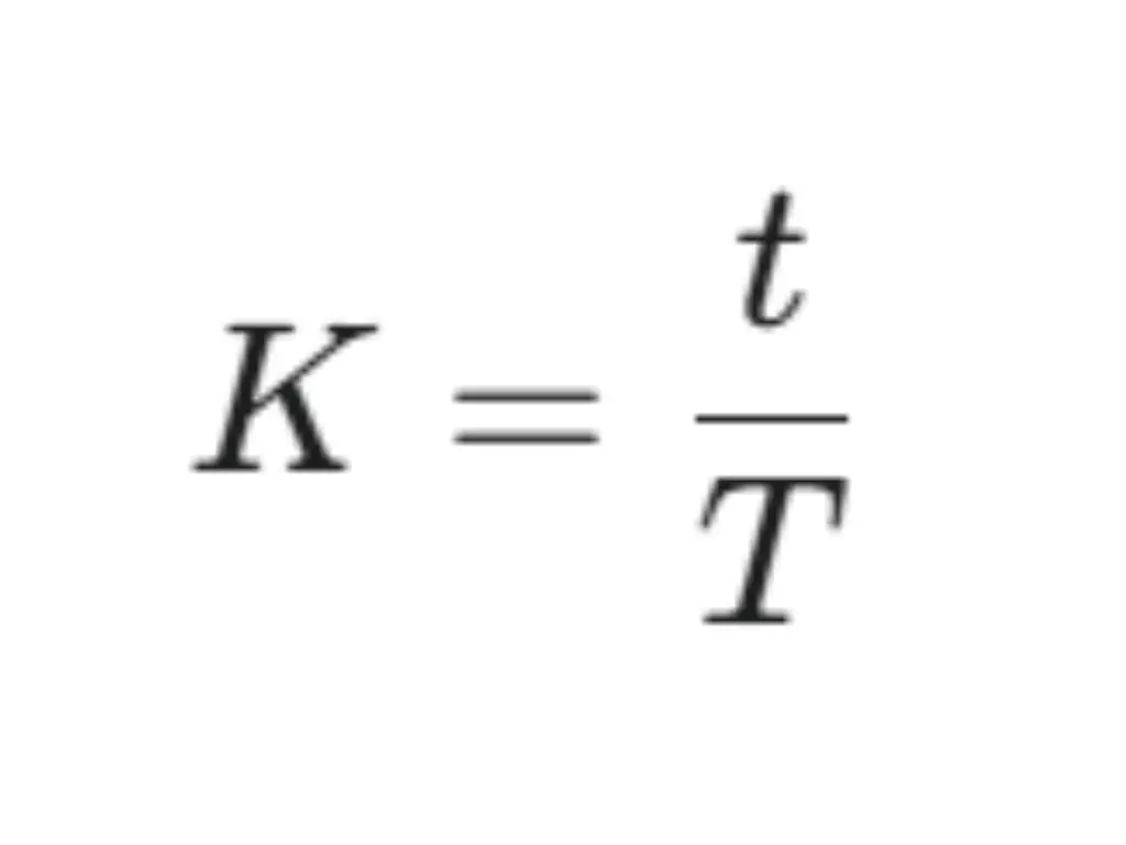
Using the correct K-Factor is essential for calculating Bend Allowance and Bend Deduction. An incorrect value leads to wrongly sized flat patterns, causing costly assembly failures and material waste.
While the most accurate K-Factor is found through testing, the table below provides industry-standard starting values based on the material and the inside bend radius (Ri) to thickness (T) ratio.
| Material Type | Bend Radius (Ri) to Thickness (T) Ratio | K-Factor (Starting Value) |
| Soft Copper, Soft Brass | Ri < T | 0.35 |
T ≤ Ri ≤ 3T | 0.40 | |
Ri > 3T | 0.45 | |
| Aluminum & Alloys | Ri < T | 0.38 |
T ≤ Ri ≤ 3T | 0.42 | |
Ri > 3T | 0.48 | |
| Mild Steel, Stainless Steel | Ri < T | 0.42 |
T ≤ Ri ≤ 3T | 0.46 | |
Ri > 3T | 0.50 |
Important Note: These values are estimates for initial design. For high-precision components, always perform a test bend to verify the exact K-Factor for your specific material and setup. Other factors like bending method (e.g., Air Bending vs. Coining) and material hardness also influence the K-Factor.
Minimum Flange Length
Flanges are the extended portions of a sheet metal part, typically formed on the edges when bending is done. The minimum flange length is the shortest length required for the metal to properly extend beyond the bend line without affecting the strength of the part. If the flange length is too short, the part may not fit securely in the die and may deform or crack during the bending process.
For the thin materials (1-2mm), the minimum flange length is usually in the range of 2 times the thickness of the material. For thicker materials, especially those that are 5mm and above, it may require 3 times the thickness or even more. A longer flange is useful in ensuring that the part is strong enough to withstand the forces that are exerted on it during use. Also, tighter bend angles may call for longer flanges in order to avoid undue stress or distortion of the material. It is also important to note that the length of the flange depends on the equipment used in the bending and handling of the material.
Bending Sequence
The sequence of the bends has a direct impact on the final part. The bending sequence must be properly determined so that there is no interference between bends and the material should not be distorted. In general, bends should be initiated at the largest angles or at the outermost sections and followed by the smaller or inner sections. This is to prevent further deformation of bent parts and to achieve precision. However, it is crucial to take into account the thickness of the material, the angles of bending and the capacity of the machine. Proper sequencing also assists in controlling the stress distribution, reduction of springback, and enhancement of the quality of the final product while at the same time enhancing the production process.
Distance Between Holes and Bend Edges
In the design of sheet metal bends, the distance between the holes and the edges of the bend is vital in determining the functionality of the design as well as the ease of manufacturing the design. If the holes are placed too close to the bend, the material may buckle, and this may lead to cracking or misalignment. This can cause a change in the shape and structure of the part as well as its appearance. On the other hand, leaving enough space helps in avoiding distortion and thus, the holes are not affected by the bending process. The ideal distance is also determined by the material type, thickness, and the bend radius of the material to be bent. In most cases, it is advisable to maintain a distance of 1.5 times the thickness of the material from the bend edge to the hole. This reduces the possibility of damaging the holes and guarantees that the part can be bent as desired. The location of the holes and bends is critical in the design of sheet metal parts in order to achieve the best results.

Distance Between Bends
The distance between bends must be calculated with care. This prevents material overlap, which could lead to distortion or poor-quality bends. Proper spacing also enables the material to be bent as desired without any obstruction. It also enables one to achieve accurate angles. The amount of required bend distance depends on the thickness of the material, the required bend radius, and the complexity of the design. In the case of thin materials, the bends can be made closer to each other, while in the case of thick materials, there should be considerable space between the bends. Interference between bends may occur due to lack of space, and this affects the quality of the part.
To ensure all these design considerations are clearly communicated for manufacturing, drawings should always dimension flange lengths from the outside surfaces of the part. At the same time, the inside bend radius for each bend must be explicitly specified, as this directly relates to the production tooling.
Optimizing Your Sheet Metal Bending Design for Cost and Quality: An Insider’s Perspective
Beyond basic design rules, true optimization links design choices directly to their impact on the factory floor. Transforming a concept into a cost-effective, high-quality part means designing for the realities of production.
Key Drivers of Bending Costs
A design’s cost is directly linked to its manufacturing time. Cost-effective parts prioritize production efficiency. This is achieved by using uniform bend radii and unidirectional bends whenever possible, which eliminates time-consuming tooling changes and part reorientations. Additionally, applying tight tolerances only where critical improves yield. A key practice is to keep holes and cutouts at a safe distance from bend lines (at least 2.5x material thickness) to avoid distortion and the need for costly secondary operations.
Bending for High-End Cosmetic Finishes
For premium enclosures, the final finish is as important as the fit, and the bending process directly impacts cosmetic outcomes. Material selection is critical; for instance, Aluminum 5052 offers a more consistent finish for anodizing than 6061 after being formed. Achieving a flawless surface on brushed or mirrored materials requires specialized non-marring dies and protective films during the bending process to prevent scratches.
A Focus on Design for Manufacturing (DFM)
The most successful projects embrace Design for Manufacturing (DFM) principles from the start. Early analysis of a design can unlock significant improvements. For example, complex geometries can be assessed for feasibility, and cost-effective methods like bump forming can be employed to create large radii without custom tools. Furthermore, joint designs can be optimized to improve the strength and aesthetics of subsequent welding. A DFM-focused approach ensures the original design intent is realized efficiently and to the highest standard.
TZR: Bending Sheet Metal Fabrication Company
At TZR, we specialize in sheet metal fabrication, offering custom solutions for your bending, cutting, and assembly needs. With over a decade of experience, we use advanced technology and skilled engineers to ensure every part meets your exact specifications. To support projects from the initial concept, our in-house ‘Design for Manufacturing (DfM)’ team, comprised of senior craftsmen, provides expert DFM analysis to handle the design, prototyping, manufacturing, and finishing of your products.
For any bending or cutting requirements, TZR offers reliable, cost-effective solutions that meet your project needs. Get in touch with us today, and let us help you turn your vision into reality with our sheet metal fabrication services.


