
The process of transforming a design idea into a physical object is one that is based on effective communication. The technical drawing is the main tool of this communication in the world of sheet metal fabrication. It is not just an image; it is the ultimate legal and technical document that interprets design intent into manufacturing reality. An efficient, cost-effective, and successful production run is based on a drawing that is clear, concise, and complete. On the other hand, an ambiguous, incomplete, or incorrect drawing is a prescription to failure, and it is open to expensive delays, wastage of materials, and sheet metal parts that are essentially unsuitable.
This guide is organized to give engineers, designers, and project managers a solid framework to create sheet metal drawings that will achieve their end goal: to allow a sheet metal fabrication shops fabricator to make your part exactly as you want it, when you want it, and at the price you want it. We shall go step by step through the necessary elements of a professional drawing, starting with the basics and ending with the final checks, so that the communication between your sheet metal design and sheet metal fabricator is one of complete clarity.
Why Your Fabricator Needs a Perfect Drawing
In order to realize how important the drawing is, it is important to realize how a modern fabrication facility works. Your drawing is not merely looked at, it is interrogated. It is the source code that CAM programmers use to extract data to laser cutters, the guide that press brake operators use to set up complex bending programs, and the ultimate arbiter to the quality control inspector. Each line, number and symbol has weight and consequence.
An ideal drawing is a risk mitigation tool. A fabricator will be able to quote with confidence when they are given a complete and unambiguous drawing, since the scope of work is clearly defined. Team members are able to place the right material in the right amount without any doubts. Their programmers and operators are able to work with confidence, taking your sheet metal fabrication project out of the digital world and into a physical sheet metal component with the greatest efficiency. This straight line between teaching and doing reduces non-value-added time, the time spent seeking clarification, waiting on updated files, or fixing preventable mistakes.
On the other hand, a bad drawing creates friction right away. A tolerance that is not defined will compel the fabricator to either make an assumption (a big risk) or to send a Request for Information (RFI), which will stall your project. The lack of reference dimensions on a critical feature implies that the press brake operator cannot program the backgauge, and a multi-thousand-dollar machine sits idle. These are not small annoyances, but direct, measurable cost and lead time effects. The drawing is not, then, a preliminary to be hurried. It is the most significant lever you have to make sure that the manufacturing outcome is smooth and predictable.
The Fabricator’s Must-Have Information First
The foundational information is what a fabricator will consult before analyzing the geometry of your part, and it is what defines the whole project. This data, including the part description, is nearly always found in the title block of the drawing. This is a very important section that is often overlooked. Every field offers a context that is critical to planning and implementation.
In your drawing you must have:
- Part Number and Description: A unique, clear part number. This is the main key that will be used to trace the part at all the production stages, including quotation and shipping. The description must be brief and precise (e.g. “Mounting Bracket, Left Side”).
- Revision Level: Manufacturing is a repetitive process. It is important to clearly state the revision level (e.g. Rev A, Rev B, 1.2) so that the fabricator is using the latest set of instructions. On the drawing, a corresponding revision table should explain what was changed since the last version. One of the most costly mistakes in this business is to produce a whole batch of parts to an obsolete revision, underscoring the critical need for version control.
- Material Specification: This must be accurate. ”Steel” is not a specification. Better is the ”A36 Hot Rolled Steel”. The correct answer is “ASTM A36 Hot Rolled Steel”. Provide the material grade, standards (e.g. ASTM, EN, JIS) and thickness needed. The material selection determines the cutting parameters, bend tooling and weld processes. Ensuring material compatibility is key.
- Thickness and Units of Material: Indicate the nominal thickness. It is also important to specify the units of measurement of the whole drawing (e.g. “All dimensions in mm” or “Unless otherwise stated, all dimensions are in inches”). The lack of notation on mixing units is a sure way to deep-seated mistakes. Pay attention to stock size and thickness tolerance.
- General Tolerances: Each dimension has a tolerance range of variation. A general tolerance block (e.g., “Linear Dimensions: X.X = 0.5mm, X.XX = 0.15mm; Angular Dimensions: 0.5”) sets the default level of accuracy that the part must be made to. This will tell the fabricator what your overall quality standard is and will affect the manufacturing process they choose. Any dimension that needs to be more precise than the general block can be specified separately.
- Finish Specification: In case the part needs post-processing, it should be indicated on the drawing. This involves such treatments as powder coating, anodizing, zinc plating or graining. Be specific. ”Powder Coat Black” is a beginning; Powder Coat, Black, Tiger Drylac Series 38, Fine Texture is a full set of instructions. Finishing is a time and cost-consuming process, and it should be considered at the initial stage.
- Company Name and Contact: Provide the name of your company and the contact details. In case there is a valid question, the fabricator must know whom to call right away. You may also include manufacturer designation numbers if applicable.
Communicating Bends, Folds, and Tolerances
The art and science of controlled deformation is the essence of sheet metal fabrication. The directions of this deformation, the bends and folds, are some of the most important information on your drawing.
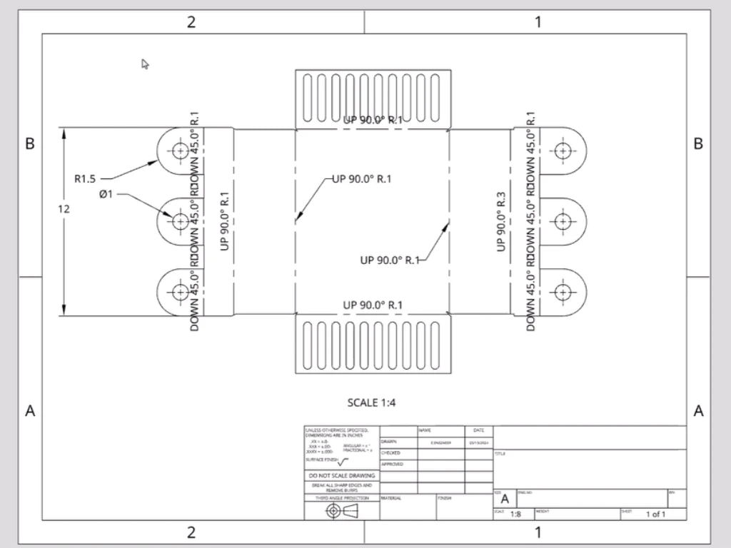
- Bend Lines: All bend lines should be shown on a 2D view, particularly on a flat pattern. They must be of a different line type (e.g. a dashed line) to differentiate them from cut lines.
- Bend Direction and Angle: Every bend should have a direction (UP or DOWN with respect to the main view) and an angle (e.g. 90 ) that takes into account the grain direction. This is usually marked on the bend line.
- Bend Radius: This is a very important, and misinterpreted, parameter. Each bend has an inside radius. This radius is not random; it depends on the type of material, the thickness of the material and the physical tooling that is available at the fabrication shop. When the radius specified is too sharp relative to the thickness of the material, cracking may occur on the outer surface. A non-standard radius can be costly to the fabricator because it may need to order special tooling. The most prudent thing to do is to design to a fabricator’s standard tooling. A rule of thumb is to have an inside bend radius that is no less than the thickness of the material.
- K-Factor, Bend Allowance and Bend Deduction: These are the values that are associated with the stretching and compressing of the material when it is bent and they are required to determine the right size of the flat pattern. Although these calculations are performed by modern CAD software, it is worth knowing what they mean. The K-Factor is a ratio that determines the location of the neutral axis in the thickness of the material. Rather than defining this yourself, it is much more efficient to model the part with the K-factor or bend deduction values that your fabricator has given you, as they will be tuned to their particular machines and tooling. What matters most is that your 3D model and the resulting flat pattern are created with realistic bending parameters.
- Tolerances on Formed Parts: Tolerances on features that span one or more bends are harder to hold tight than those on features that are all within a single planar face. Tolerance stacking of the material thickness, bending angle, and flange length can cause a large variation. Be practical with your formed tolerances. If the location of a feature is really critical, it may be possible to machine or punch it after forming, but this will increase the cost. It is strongly recommended to discuss critical feature tolerancing with your fabricator.
Providing a Clear and Usable Flat Pattern
The physical part is the offspring of the flat pattern. It is the 2D image of your component prior to any bending. This is the file that will be sent to the laser cutter or turret punch press. This is where the precision of the completed piece starts.
The full drawing submission must contain a fully dimensioned view of the flat pattern. This perspective is an important cross-reference to the 3D model and the views that were formed. Besides the flat pattern view on the PDF drawing, you are expected to provide the fabricator with the flat pattern in a usable digital format, most often a DXF or DWG file.
A flat pattern file that can be used should contain:
- 1:1 Scale: The file should be exported as true 1:1. Any scaling factor will cause a part that is not sized correctly.
- Clean Geometry: The file must only have the geometry that is needed to cut. Eliminate any title blocks, dimensions, construction lines or other unnecessary items. The file must be clean, with closed profiles.
- Separate Layers (Recommended): One of the best practices is to put different features on different layers. As an example, outlines on one layer, bend lines on another, and any etched part numbers or markings on a third. This enables the CAM programmer to simply allocate various machine operations to the right geometry.
Although a 3D model is necessary to comprehend the end shape, the 2D flat pattern is the file that will be used to run the main manufacturing process. It is a non-negotiable step to provide a clean and accurate version of it.

File Formats: Delivering Your Drawing for Fabrication
A meticulously prepared drawing is only effective if it’s delivered in a package that your fabrication teams can efficiently use. In a modern shop, different departments rely on different file types to perform their specific tasks. Submitting a complete package prevents misinterpretation and accelerates the entire process. Your submission should always include three key components:
- The PDF: The Master Document and Legal Arbiter: The PDF drawing is the single source of truth for your project. It is the “contract” that contains all critical information in a human-readable format. The quoting department uses it to assess complexity, the engineering team refers to it for instructions, and the quality control department uses it as the final standard for inspection. It must contain all views, dimensions, tolerances, notes, and the completed title block. If there is a discrepancy between the CAD model and the PDF, the PDF is almost always considered correct.
- The 3D Model (STEP/STP): The Key to Visualization and Forming: A 3D model, preferably in a universal format like STEP (.stp or .step), is essential for understanding the part’s final geometry. It allows the fabricator to rotate and inspect the part from any angle, clarifying complex features that might be ambiguous in 2D views. For the press brake operator, the 3D model is invaluable for planning the bending sequence to avoid tool collisions.
- The 2D Flat Pattern (DXF/DWG): The Direct Machine Instruction: This is the most critical file for the actual cutting operation. As detailed in the previous section, the DXF or DWG file is not for human interpretation; it is the direct instruction for the CAM software that programs the laser cutter or turret punch. Providing a clean, 1:1 scale DXF/DWG file saves the fabricator from having to create one from your PDF, which eliminates a potential source of error and saves time.
These three file types—PDF, STEP, and DXF/DWG—form a complete, professional submission package. Providing all three empowers your fabricator to move from quotation to production with maximum speed and confidence.
Thinking Like Your Fabricator: DFM Insights
It is one thing to design a part that can be made. Another level of engineering altogether is designing a part that can be made efficiently. This is Design for Manufacturability (DFM). It entails active thought of the fabrication processes and limitations in the design phase. Thinking like your fabricator will allow you to make minor design modifications that will make a significant positive difference in cost and quality.
These are some DFM principles:
- Standardize Tooling: Is it possible to use the same hole size all throughout your design rather than three slightly different ones? Is it possible to design bends using the standard 1.5mm radius of the fabricator rather than a custom 2.0mm radius? The standardization of features minimizes the tool changes and setups, which directly minimizes the labor costs.
- Hole and Feature Placement: Holes and other features should be placed sufficiently far away from bends to prevent deformation. One general guideline is that the edge of the hole should be at least 2.5 times the thickness of the material and the bend radius away from the beginning of the bend.
- Make it Simple: Is a bracket really going to require five bends, or can a minor redesign get the same job done with three? The fewer the bends, the quicker the production and the less the tolerance error accumulated.
- Think Assembly: Does your part fit into a larger assembly? Are the fastener locations tool-friendly? Is it possible to add self-locating features such as tabs and slots to make assembly foolproof?
A DFM mindset changes the design process into a silent partnership with the factory floor.
Why Partner with TZR for Sheet Metal Projects?
Global Proven Manufacturing Capability
- 11,000㎡ wholly-owned factory equipped with a 20kw laser cutter (±0.02mm precision), ensuring top-tier quality.
- 98% yield rate guaranteed: Our 6-stage quality control covers raw materials to final inspection, adhering to ISO 9000 standards.
- Trusted by clients in 30+ countries: Delivering complex sheet metal solutions for automotive, medical devices, 3D printers, and renewable energy.
- Mastery of Diverse Materials: Expertly handling steel, stainless steel, aluminum, copper, brass, and more.
Beyond Fabrication: Added Value for Your Success
- Complimentary DFM Analysis: Our 30-year experienced engineering team provides proactive manufacturing optimization advice.
- 7-Day Expedited Delivery Channel: Supported by our self-owned logistics system for urgent global shipments.
- Flexible Production: Powerful supply chain network for any quantity, from prototypes to large-volume production with competitive, personalized pricing.
Partner with TZR to leverage decades of manufacturing knowledge, bridging the gap between design theory and production reality. We help mitigate risks, eliminate guesswork, and ensure exceptional results.
Act Now: Upload your drawings to [sales@goodsheetmetal.com] to receive:
✅ Professional quote within 2 hours
✅ Customized DFM optimization plan
Choosing the Right CAD Software for Your Drawing
In the process of drawing a sheet metal to be fabricated, it is important to choose the appropriate CAD software that will not only make your designs accurate, but also optimized to manufacturing processes. The quality, clarity and manufacturability of your drawings will be directly influenced by the software you use. Knowing the advantages and disadvantages of each tool may assist you in making the most appropriate decision regarding your design and fabrication requirements. The table below compares some of the most popular CAD software in the industry, their main features, strengths, and weaknesses.
| Feature | SolidWorks | AutoCAD | Creo Parametric (Pro/E) | CATIA |
| Ease of Use | – Relatively easy to learn – User-friendly interface – Intuitive – Fast learning curve – Good community support | – Relatively easy to learn – 2D drawing-based interface – Quick to master | – Intermediate level – Suitable for large machine design – High-performance machine capabilities | – Very difficult – Powerful but complex interface – Steep learning curve |
| Software Limits | – Moderate complexity – Suitable for most machine design needs – Can handle large assembly models | – Moderate complexity – Limited 3D capabilities – Weak 3D modeling | – Complex – Excellent for large and complex assemblies – Powerful 3D modeling capabilities | – Extremely complex – Best suited for aerospace, automotive, and shipbuilding design |
| Main Features | – Easy to learn – Good interface – Easy to operate – References to design models – Suitable for standard machinery and parts design | – 2D drawing standard – Weak 3D capabilities – Suitable for drafting and schematic designs | – Powerful parameters and constraints – Superior for engineering design – Robust for large scale | – Excellent for complex surface and 3D modeling – Top-notch for industrial and aerospace use |
| Key Advantages | – Easy learning – Fast start-up – Suitable for small and medium-sized enterprises – Suitable for educational use | – Common 2D function – Good for architectural design – Can handle complex 2D designs | – Strong parameters and constraints – Good for engineering design and simulations | – High-end product design – Multi-disciplinary applications like aircraft, ship, and automotive design |
| Key Disadvantages | – Some difficulty with large sheet metal assemblies – Good for most machine design models | – Less effective for 3D modeling – Suitable for 2D only | – Difficulty in 2D modeling – Requires advanced knowledge | – Requires specific training – Expensive software – Highly complex |
| Special Features | – Excellent for machine design – Parts processing – System integration | – Standard for 2D schematic and drafting work | – Advanced modeling tools – Can simulate and design large-scale systems | – Excellent for systems integration – Works with complex engineering and design systems |
Summary:
- SolidWorks: Full-featured, simple to learn and operate, applicable to the majority of mechanical design requirements, particularly to small and medium-sized companies and schools. SolidWorks is a good option when you are a novice or when you have to start fast.
- AutoCAD: The standard in the industry of 2D drawing, very versatile. AutoCAD is an indispensable solution in case your primary work is 2D drafting or you require a universal drawing platform.
- Creo Parametric: Strong parametric functionality and great surface modeling, best suited to users who have high requirements of design flexibility and complex surfaces. Creo is more professional in case you require to work with complex product design and analysis.
- CATIA: The “king” of functionality, which is specifically aimed at designing complex products in high-end manufacturing industries (aerospace and automotive). CATIA is the industry standard in these industries. Nevertheless, it has a steep learning curve and is rather costly, which is why it is more applicable to large businesses and professional teams.
Avoiding Common Drawing Rejection Mistakes
A drawing is “rejected” when a fabricator cannot proceed without further clarification. This is a complete stop in your project’s momentum. Most rejections are caused by a handful of recurring, and entirely avoidable, mistakes.
- Conflicting Dimensions: The classic error. A feature is dimensioned as 10mm in the front view and 10.5mm in the top view. The programmer has no choice but to stop and issue an RFI.
- Missing Dimensions: A feature is shown, but its location or size is not defined. The fabricator cannot guess your intent. Every feature must be fully and clearly dimensioned.
- Impossible or Impractical Tolerances: Specifying a tolerance of ±0.01mm on a 500mm formed dimension is functionally impossible for standard sheet metal processes and will be immediately questioned. Be realistic and only apply tight tolerances to truly critical features, ensuring accurate sheet metal.
- Inconsistent Revision Levels: The PDF drawing shows Rev C, but the attached DXF file is named with Rev B. Which one is correct? This ambiguity must be resolved before work can begin.
- Lack of Flat Pattern: Submitting only a 3D model or formed views without a corresponding flat pattern forces the fabricator to create their own. This introduces the risk that their flat pattern will not match your design intent, especially if non-standard bend parameters are required.
Your Final Pre-Quotation Submission Checklist
Before you attach your files to an email and press send, perform one final review. Use this checklist to catch the most common errors and ensure your submission package is professional and complete.
- Views: Are all necessary views present (orthographic, isometric, flat pattern, detail views)?
- Title Block: Is every field in the title block complete and correct?
- Revisions: Is the revision level clearly marked and consistent across all documents?
- Dimensions: Are all features fully dimensioned without any conflicts or omissions?
- Tolerances: Are general and specific tolerances clearly defined?
- Bend Information: Is every bend defined with a radius, angle, and direction?
- Material & Finish: Are the full material and finish specifications present?
- File Formats: Are you including both a PDF drawing and the necessary CAD files (e.g., STEP for the 3D model, DXF/DWG for the flat pattern)?
- File Naming: Are your files named logically, including the part number and revision? (e.g.,
100254-REV-C-Bracket.pdf)
Completing this checklist diligently is the final act of preparation. It signals to your fabricator that you are a detail-oriented professional, and it paves the way for a smooth and efficient quotation and manufacturing process. The effort invested here will be returned tenfold in the quality of the service you receive and the excellence of the final product.


